Table of Contents
Journal Name : TESS Research in Research and Reviews
Gyeongsang National University, Metallurgical and Materials Engineering Department, Chinju 52828, Korea
Corresponding author: Xu R, Gyeongsang National University, Metallurgical and Materials Engineering Department, Chinju 52828, Korea; E-mail: 13953575073@163.com
Received date: 2 April 2023; Accepted date: 3 April 2023; Published date: 5 April 2023
Copyright: © 2023 Xu R. This is an open-access article distributed under the terms of the Creative Commons Attribution License, which permits unrestricted use, distribution, and reproduction in any medium, provided the original author and source are credited.Download PDF
Abstract
Currently, the wind generator is gradually increased recently according to new status, so the dynamic and kinematic equation is needed to use to them as well. In this paper the power with speed and mass in wind turbine blades is discussed in detail. It is observed that in the low rotation the power will increase with the long wind blade. This paper will express the all kinds of these respects to adopt curve to explain the relation of them. It is observed that if the wind speed is 3.8m/s to 6.8m/s the average power will decrease from 35kW m/s to 230kW under the mass of wind turbine blades are from 3.3tons to 1.6tons at attack angle 40° that becomes sine distribution. The increasing α and β is from 0 to 83° and from 0 to 20° to increase the power respectively. When the angle of attack α increases from 83° to 180° the power and force decreases too. There is a certain power changes in wind turbine with less than 50kW and force with less than 10kN with β changing from 0 to 20°. Only rotating speed reaching a certain value can the maximum effect be.
Keywords: Wind generator; dynamics; wind speed; equation; Turbine blades; α and β; angle f
Introduction
The wind turbines are the latest to enter the market. To build wind turbines for environmental protection is an inevitable trend in the world. Although it is not as powerful and efficient as other conventional thermal and hydroelectric generators, it is replacing them with its abundance and sustainability. In places like Yantai city in Shandong province, huge wind turbines are set up in groups on hillsides to bring the latest wind energy utilization, and it appears in all over the developed countries. These huge structures have an unexpected power generation effect by rotating the same huge impeller. Therefore, this paper discusses its energy utilization status from its efficiency and quantity to evaluate its physical significance. Its processing is the most important, and then other problems etc. In 15 to 20 years since a wind turbine could be used, the calculations are low. In this time it would spin 2.16 million times and calculate energy up to 100 million Joules and 10 million Watts of power. That’s 50 times the size of a small city in the 70s and 80s. With 500 such generators, the total power would be 5 gWs and 50 gJs, about one-fifth of the 22,000 mWs of installed capacity of the three gorges reservoir. On the other hand the strong winds can quickly make up for their use, filling the countryside with the energy from wind turbines. At present, the number of wind turbines used by European and American countries is increasing year by year. China also is needed to catch up and keep in line with the international developed level. Therein several thousand such turbines would be comparable to the Three Gorges Reservoir, China’s biggest generator. This means that an average medium-sized city can have nearly a quarter of the power generated by it. Because these generators run 24 hours a day, there is a constant supply and quantity of electricity to these big cities without the interruption of power supply. The perfect storage function will really bring energy effect. The storing energy from strong winds for later use is an urgent problem for wind turbines. If you put it on a windy mountain, it will continue to generate electricity. At this time to set the number of more engines, in order to prepare for sporadic scattered wind brings the problem of insufficient wind power. The wind and water hybrid power generation is needed to solve the problem of energy shortage and continuity. Seawater utilization should also be included in the plan such as the use of tide and high tide, etc.. In the case of typhoons and tsunamis, their strength and fatigue strength, is needed to guarantee. Therefore, the bending strength of the ground and straight head of the generator should be guaranteed to avoid economic losses. If the broken parts fly to buildings or roadside facilities, they can cause a second damaging effect, causing damage to public facilities and causing problems for the country such as repair. As talked above, if there are energy reserved devices and methods to absorb this big source into them the abundant source will be maintained for us to use month by month. We can transform it into another style like wide water reservoir within leisure and abundant time and use it in necessity [1-12].
Model Establishment
The parameters of German Nordex N60, S70 and S77 models are shown in Table 1. The wind generator has the overall layout of the wind turbine with blade length l and it rotates at the speed of ω. From Figure 1 the wind speed v and force F and the wind speed and direction. The pitch angle β which is angle of blade chord and rotational plane obtains x-y direction of velocity and force of component, is the inlet air speed v in generator blade vxˎ vy and force Fxˎ Fy. Angle of attack α which convergence speed being the angle of inlet air and rotational relative synthesis speed and blade chord obtains x’-y’ direction of velocity and force of component is the main speed in turbine blade slope area. Flow angle f which is the angle of convergence speed and rotational relative synthesis speed.
Since the uniform wind speed acts on the blade, then
(1)
Here, according to the law of conservation of energy
(2)
Here I is the inertia product, and m is the mass of the blade of the wind wheel.
Table 1: Data of Nordex wind turbine.
| N60 | N60 | S70 | S77 |
| P, MW | 1.3 | 1.5 | 1.5 |
| V, m/s | 60 | 70 | 77 |
| L, m | 29 | 34 | 37.5 |
| Vrate ,m/s | 15 | 13 | 13 |
| Mrate ,tons | 5 | 5.6 | 9.9 |
| N r/m | 12.8 | 19 | 17 |
| Vin ,m/s | 3 | 3 | 3 |
| Vout ,m/s | 25 | 25 | 20 |
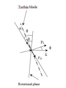
Figure 1 schematic of wind speed and force resolution.
(3)
Here I is the inertial product, omega is the angular velocity, m is the blade mass, and v is the blade velocity.
(4)
P is blade power, Q is kinetic energy, and t is time because
Therefore, the calculation formula of acceleration is (5)
And the force calculation formula is (6)
Since it has (7)
Take place of above formula, it has
(8)
On the other side, because of
(9)
So there is the below equation
(10)
Here n is rotation r/m; vL is the wind speed m/s; vd is the rotation speed m/s; f is angle.
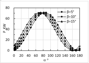
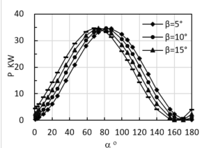
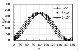
The calculated results are shown in Figure 2 and 3. Figure 2 (a~e) is the dynamic simulation relationship of the rotating a cycle of the wind turbine blade. The power & force and α angle attack are shown in Figure 2 (a~d) and Figure 3(a~d) respectively under the wind speed of 10.8 m/s and 6.8m/s at angle of attack 40° amplitude. The Figure 2 and Figure 3 forms into sine distribution, between speed and angle of attack is a sine amplitude. Figure 2 is the power with the increase of angle of attack α becomes sine curve. The average force is from 25kN to 7.5kN. In order to improve the efficiency, the three blades are taken together so that they act continuously with a difference of 120° to produce energy and output energy like a three-phase star generator. The most effective way to increase power is to increase speed, so high speed is the main factor to improve efficiency. As shown in Figure 2, the corresponding power generation energy increases with the increase of rotating speed. So we think the requirement is to wind speed. The second is blades mass. The more wind speed and blades mass, the more energy. Therefore, the speed and mass greater.
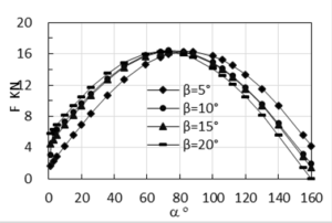
In Figure 2(a~d) and Figure 3(a~d) the power and force increases with the increasing α changes 0-80°& β changes 5-20°. The power and force becomes periodical sine curve. The maximum average power is 300kW and force is 25kN at α is 40° and β is 5°. There is a certain power changes in power with 150kW and force with 15kN. When angle of attack α increases from 83° to 180° the power and force decrease too while with decreasing pitch angle β the power and force increase from 5° to 20°.
a) P, β is pitch angle, v=3.8m/s, m1=3.3tons
b) P, β is pitch angle, v=3.8m/s, m1=1.6tons
c) P, β is pitch angle, v=6.8 m/s, m1=3.3tons
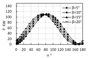
d) P, β is pitch angle, v=6.8 m/s, m1=1.6tons
Figure 2: Relations of power and angle of attack α in a cycle under v=3.8~6.8m/s and m1=1.6~3.3tons.
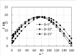
a) F, β is pitch angle, v=3.8m/s, m1=3.3tons
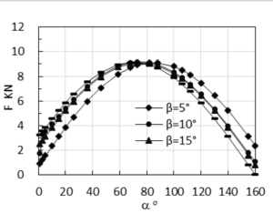
b) F, β is pitch angle, v=3.8m/s, m1=1.6tons
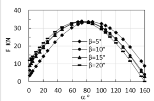
c) F, β is pitch angle, v=6.8m/s, m1=3.3tons
d) F, β is pitch angle, v=6.8m/s, m1=1.6ton.
Figure 3: Relations of force and angle of attack α in a cycle under v=3.8~6.8m/s and m1=1.6~3.3tons.
Figure 3 shows the data between force and angle of attack with a blade mass of 3.3 tons and 1.6 tons at a speed of 3.8m/s and 6.8m/s at the blade length is 34m. It can be seen that in the first 80° the force drops sharply to maximum force, then it gradually increases. This indicates that the moment of inertia Jc is at work, that is, the huge blades with a mass of 1.6 tons~3.3 tons are slowly driven by the large start-up energy. It can be seen from Figure 3 (a and b) that the force increases near linearly with the increase of the speed of arrival. It indicates that a little amount of force is needed at the beginning of the drive, and the greater the mass and the greater the speed, the greater the force required. The rotation energy consumption is too large in order to meet the requirement of conversion to dynamic energy with bigger mass of blade and smaller speed. In this way, power consumption and efficiency will be lower, which is not conducive to power generation. So the right amount of speed is the basic to ensure the maximum power. Too much speed requires more force, too little speed does not play its due role. From the above analysis, it can be seen that only if the rotating speed reaches a certain value can the maximum effect be guaranteed in terms of the efficiency conversion.
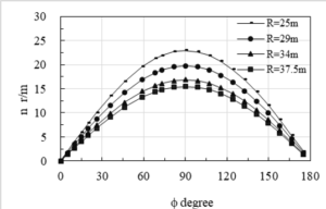
Figure 4: Relations of totation and angle f with turbine blade radius R=25m~37m under v=60m/s.
Conclusion
It is found that the lower rotation transforms into the bigger power with the longer blade length in this paper. When the wind speed is 6.8m/s and then 3.8m/s under the pitch angle at 40° the maximum average power will become sine distribution with 230kW and 70kW respectively. The increasing α and β results in increasing force with maximum 34kN to 20kN power and force when the pitch angle α changes from 0 to 83° and the angle of attack β changes from 0 to 20° respectively. When the angle of attack α increases from 83° to 180° the power and force decrease too. There is a certain power changes with less than 50kW and force with less than 10KN with β changing from 0 to 20°. The power consumption and efficiency will be low with low wind speed. Only rotating speed reaching a certain value can the maximum effect be.
References
- Li JQ. Design evaluation of key mechanical components of wind turbine. Quality Certification. 2019; 8: 67.
- Liu M, Yuping S. Motor and drag. China Machine Press. 2016; 163.
- Feng QX. Electromechanical drive control. Huazhong University Sci Technology Press. 2016; 26.
- Wang H, Fan HZ, Shuaibin L. Wind turbine blade modeling and finite element analysis. J Shanghai Electric Power University. 2016; 3: 258.
- Xu H. Research on a new small wind turbine blade modeling method. Electrical Manufacturing. 2011; 5: 46.
- Fei WL. Design of hydraulic variable propeller system for wind turbine. Hydraulics Pneumatics Seals. 2019; 10: 58.
- Liu N. Power curve acquisition method of wind turbine. Ship Engineering. 2019; 1: 291.
- XJ Yao, J Song, Principle and application of wind turbines. China Machine Press. 2020; 43.
- Li M. Probabilistic optimization design of wind turbine gear system and power reliability. General Machinery. 2019; 9: 18.
- Yin P. The study on precise modeling of wind generator’s blade under integrated application of multi-software. Machinery Design Manufacture. 2010; 5: 137.
- Wang ZD, Hu ZY. Based on solid works the wind generator blade Modeling. J Inner Mongolia University Technol. 2011; 2: 129.
- Yang J, Xie W, Zhang W, Wang SF, Yang SS. Research on the performance improvement of vortex generator installed on the blade of fixed-pitch wind turbine. Mechanical Electrical Engg Technol. 2019; 10: 124.